This is an assembly instruction for the Goblin-EXP and the Electro Harmonix Pitch Fork. You can use it as a guideline for installation of the Goblin-EXP in other devices. All the measurements and configurations are only as an example for installation in other devices and don’t need to be made for the Pitch Fork. The Goblin-EXP is already set for the Pitch Fork when you buy it
On the main site for the Goblin you’ll find the most recent installation manual. Always have it handy and in doubt, the manual is right. We will first disassemble, then solder all wires to correct points on the Pitch Fork, drill the holes and then connect the wires to the Goblin.
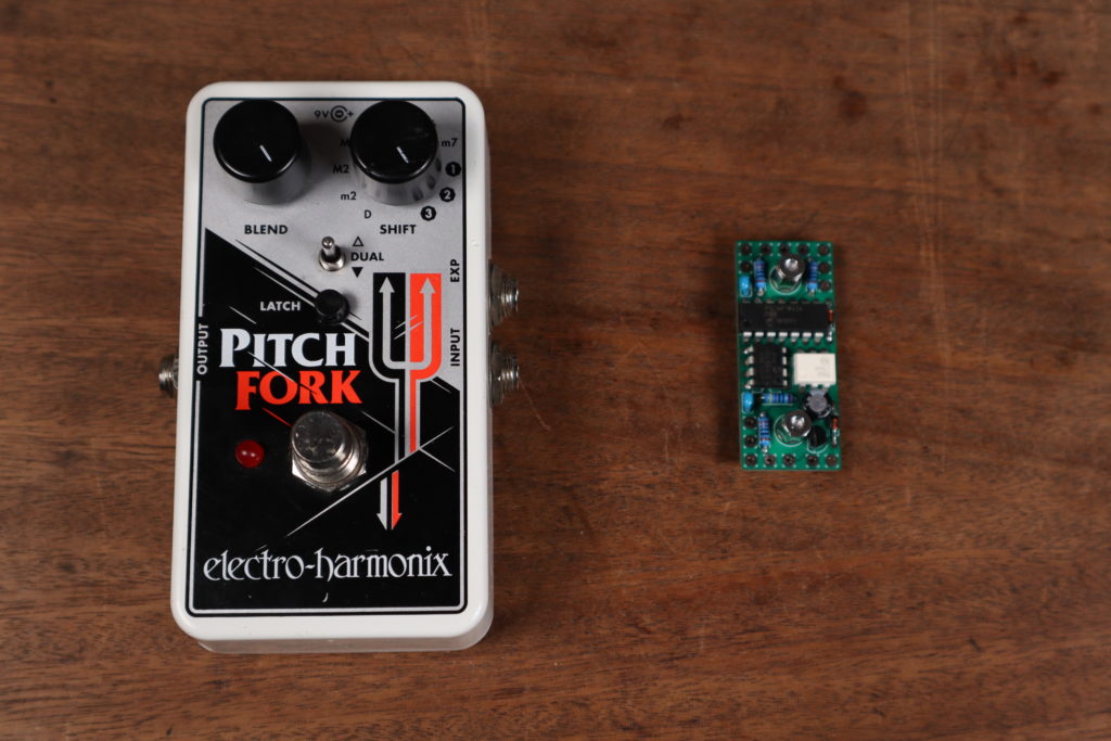
Step 1: Disassembly
First remove the Blend and Shift knob. They can sit very tight. Use a hairdryer to warm them up a little and just pull them off. Remove the screws from the bottom plate and all the nuts. Remove the PCB from the enclosure. You can now desolder and remove the 9V battery clip.
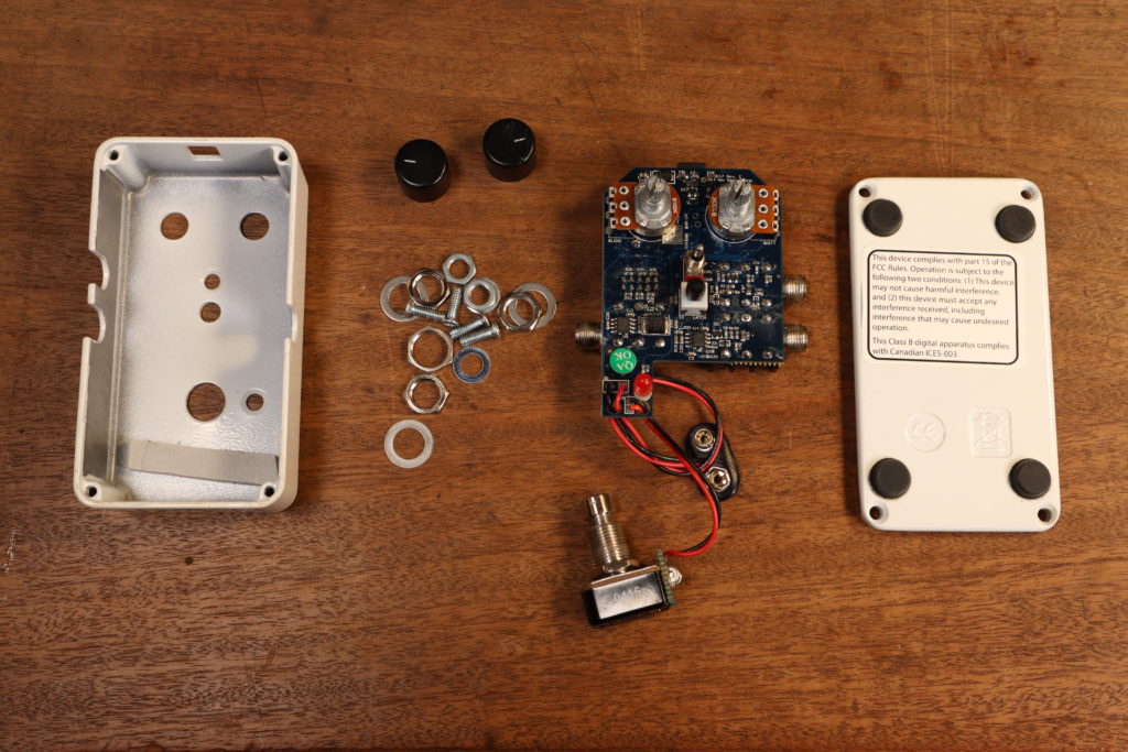
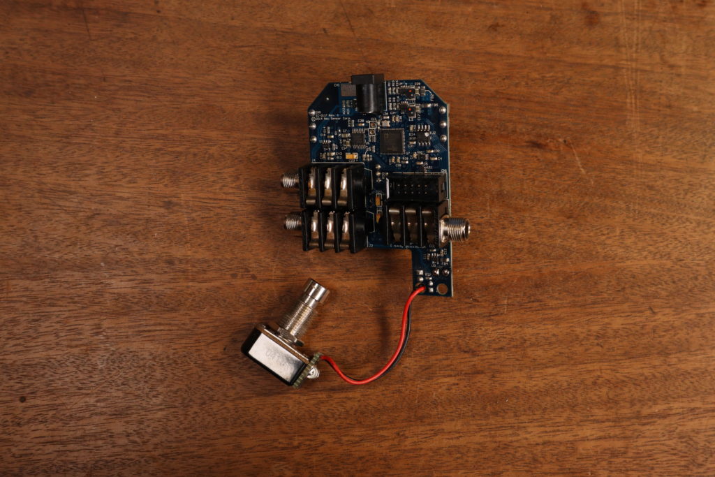
Step 2: Power Supply
First we solder the wires for the power supply to the bottom side of the DC jack. Check which one is the 9V and which one the GND pin.
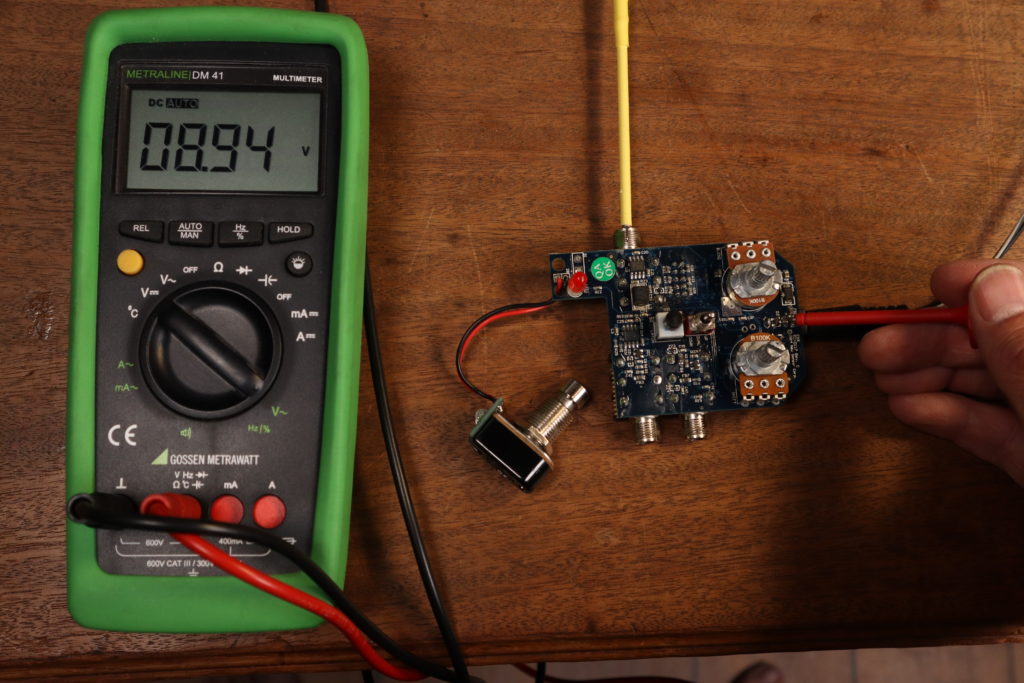
Step 3: LED
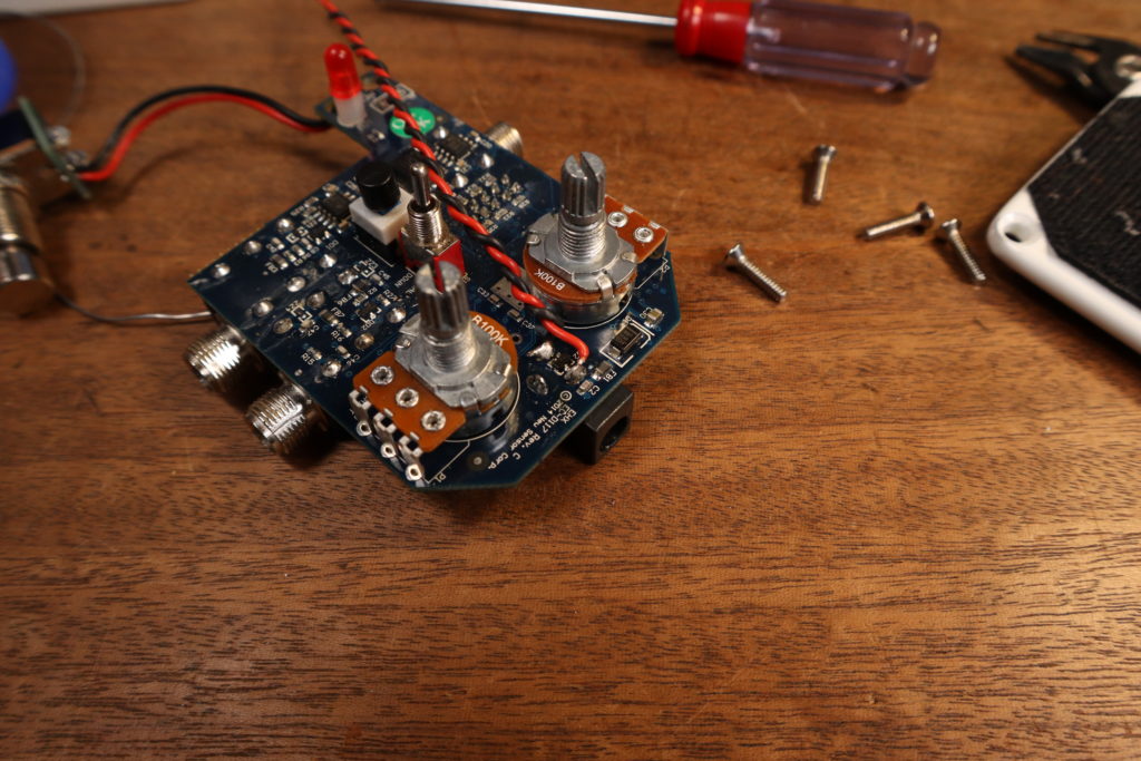
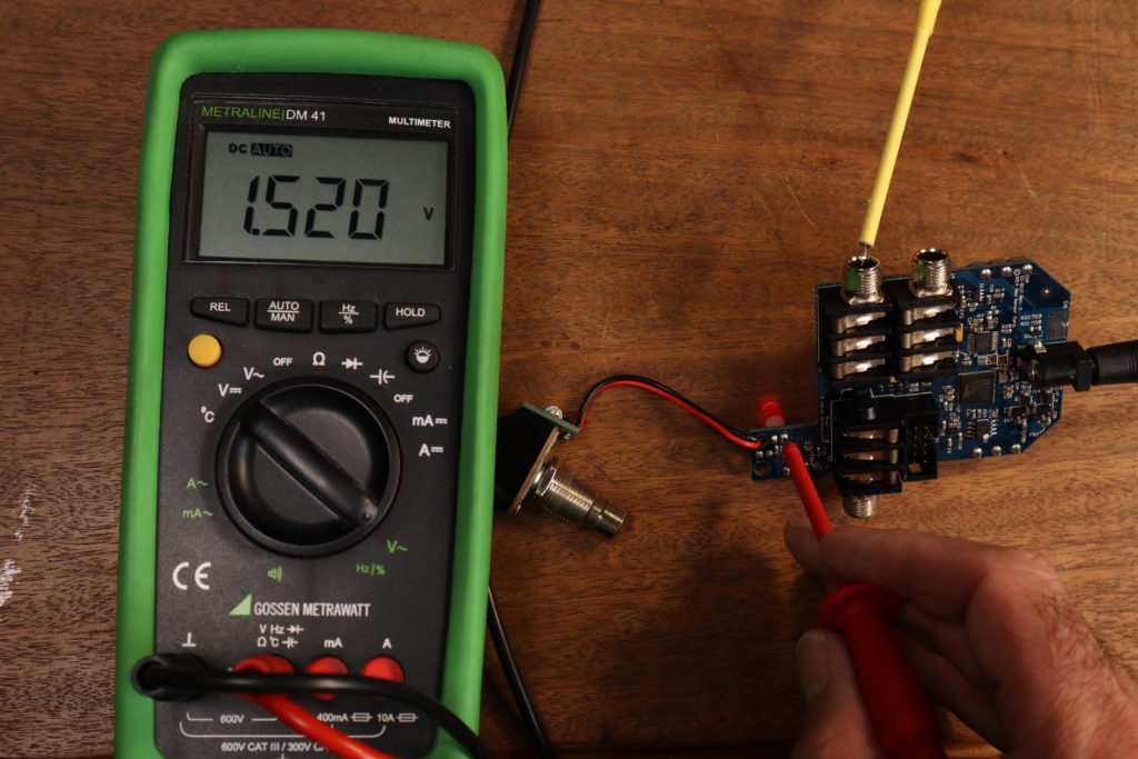
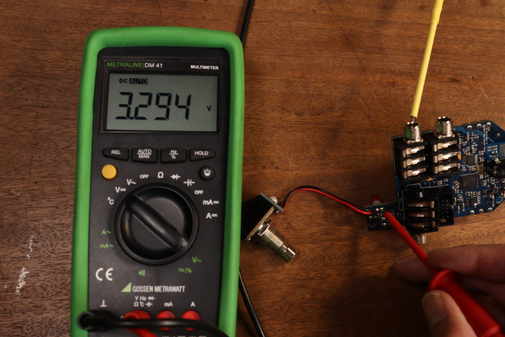
Now we solder a wire to the LED. Check which LED pin is the active pin. That is the pin that changes the voltage when you switch the pedal on and off. For the Pitch Fork it’s the one with the square PCB pad. Solder a wire there.
Step 4: Mode Switch
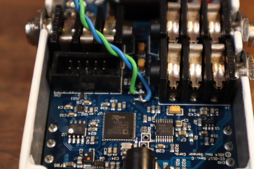
You’ll find the pins for the mode switch beside the EXP jack. Solder two wires, one on the middle pin and one on the pin facing the DC jack.
Step 5: Expression Jack
Expression jacks are usually all wired the same way. But to be sure we don’t exceed +5V or running into some weird wiring we didn’t expect it’s better to measure the pins. Usually the ring is +5V and goes on one pin of the potentiometer and tip goes to the other pin (usually the wiper) of the potentiometer. The third pin of the potentiometer goes to GND, this is already done on the Goblin-EXP.
Step 6: Bypass Switch
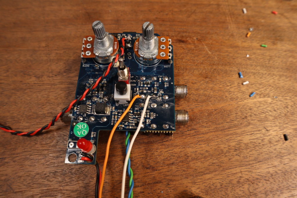
For the bypass switch we need to make sure we connect the positive line to the Goblin. This is the line that is at +3.3V or +5V. Don’t rely on wire colors here. Desolder the wire of the positive side from the switch. It is connected to the Goblin later. Use another wire and connect it to the switch like the orange one in the picture.
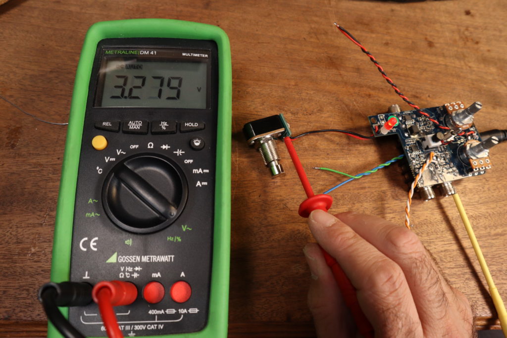
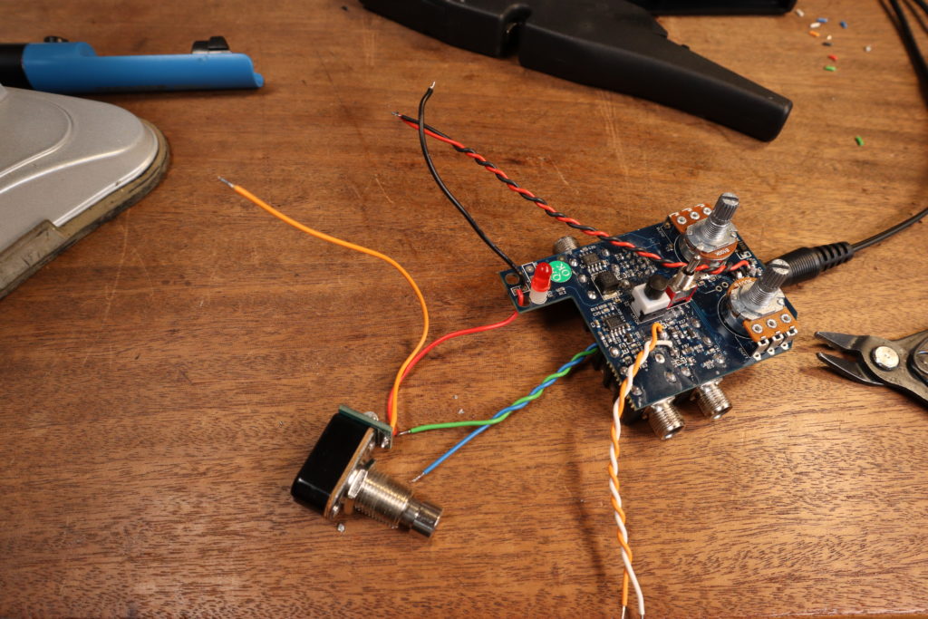
Step 7: Drilling
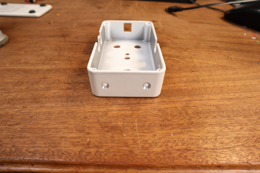
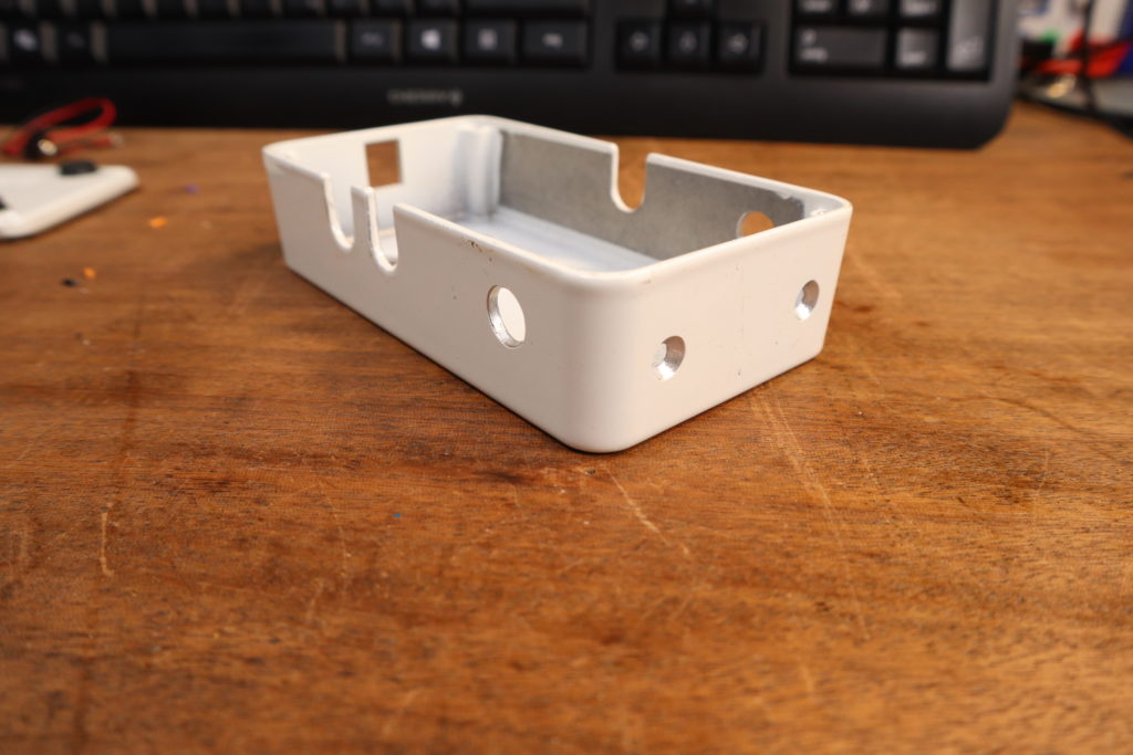
Now we have all the wires we need soldered to the PCB of the Goblin. It’s time to drill the enclosure. For the holes of the Goblin I use 3.3mm, anyway, the screws are M3. Horizontally, place the holes aligned with the center with a distance of 33mm apart. Vertically you can also center the holes. Be precise in hitting the center, it’s going to be tight in there.
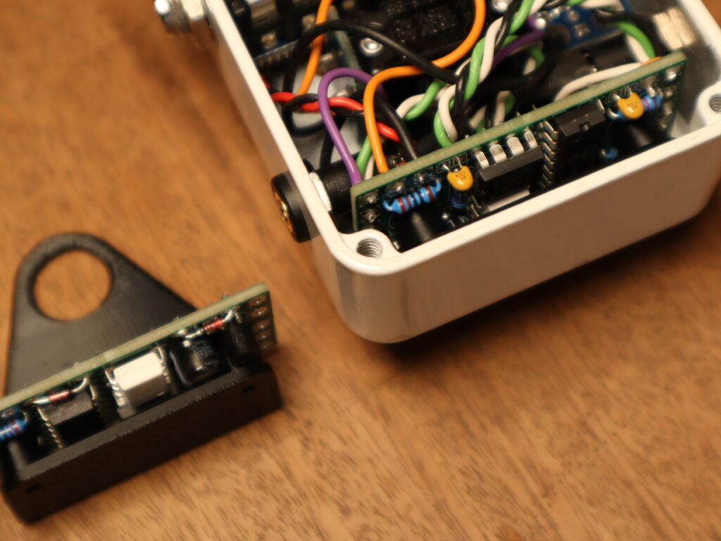
There is now a 3D printed monuting bracket available in the shop. No need to drill holes for the Goblin anymore. Only holes for the TRS sockets are needed.
The holes for the TRS Sockets are 8.5mm. I have them around 20mm from the bottom and 10mm from the side of the base plate.
Step 8: MIDI sockets
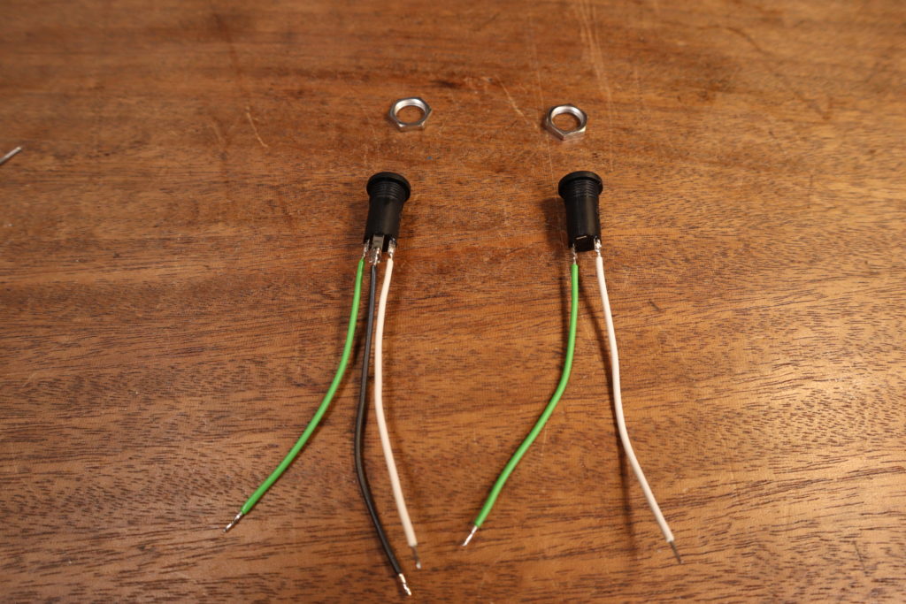
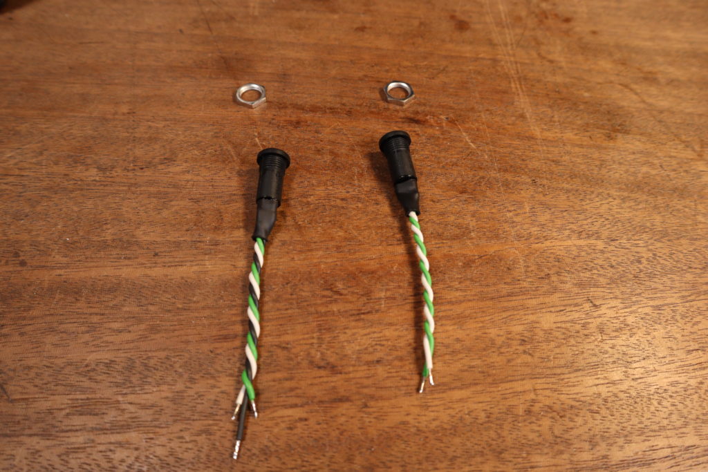
Now we need to prepare the MIDI sockets by soldering wires to it, like in the pictures below. The MIDI in socket doesn’t have a GND/Sleeve wire. You can remove the lug all together. I like to put a piece of heat shrink on it and twist the wires. This has no technical advantage. It just looks nice and it’s a bit cleaner inside the enclosure.
In the picture the white wire goes to the tip, the green wire goes to ring and black to sleeve.
Step 9: Connecting the Goblin
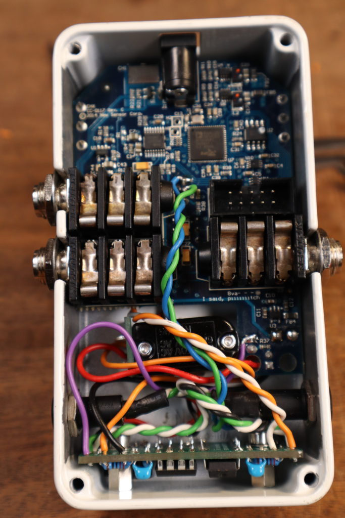
Next we place the PCB back in the enclosure and start to connect the wires to the Goblin. It now should look like this.
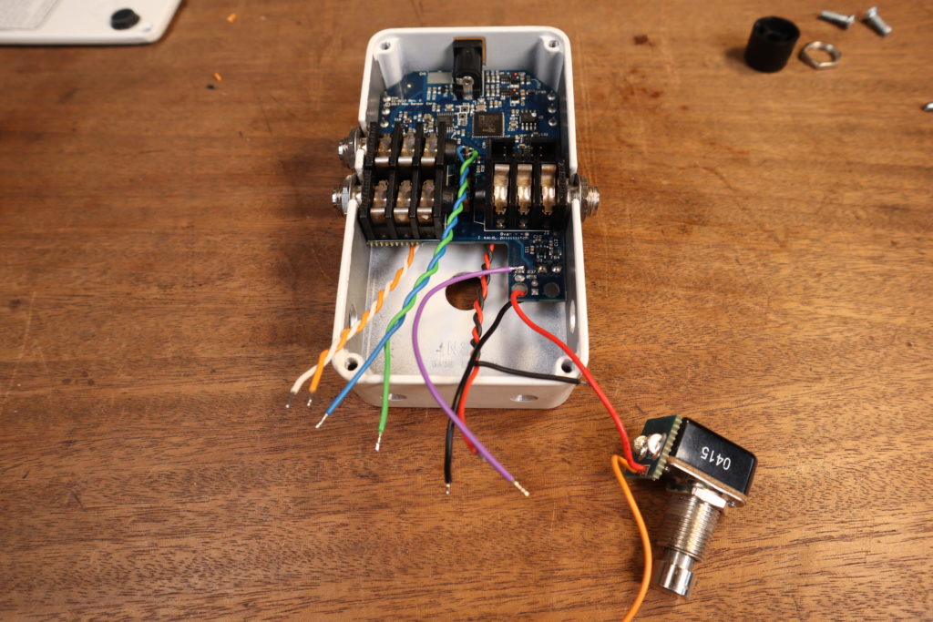
As a quick overview, the wires are connected like this:
- Red (Positive side of the DC jack): +9V
- Black (GND side of the DC jack): GND next to +9V
- Purple: LED1
- Orange (Switch): SW1
- Black (PCB, was at the Switch before): RLY1
- Green (Mode Switch): RLY2
- Blue (Mode Switch): SW2
- White (EXP ring): EXPA
- Orange (EXP tip): EXPW
But let’s take it one by one and include the MIDI sockets. First the power supply.
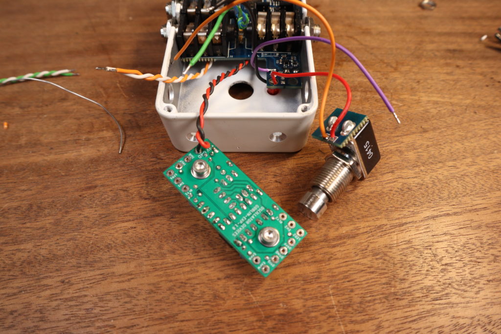
Then the MIDI in socket. White is tip and goes to ISIG, green is ring and goes to IREF
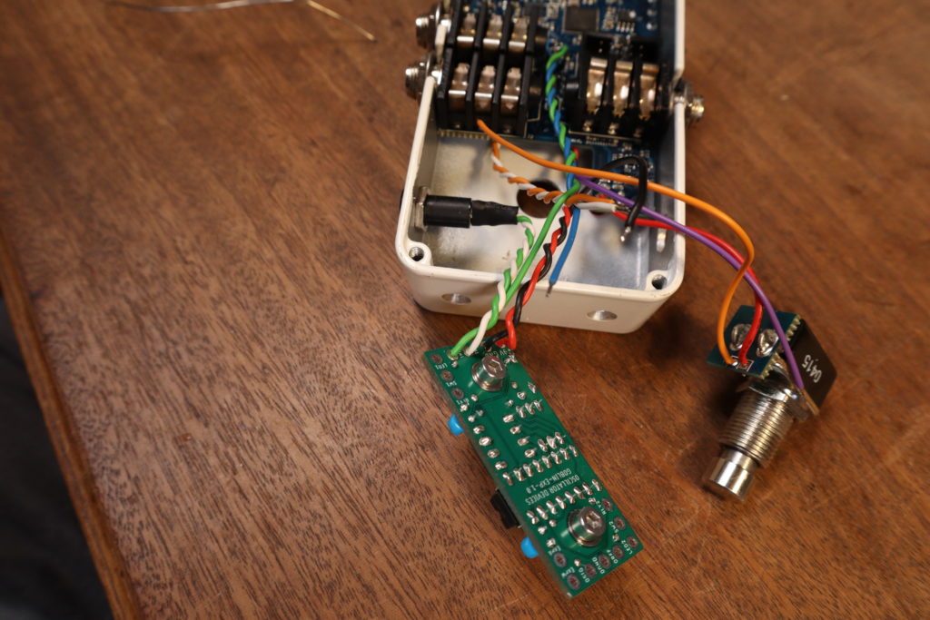
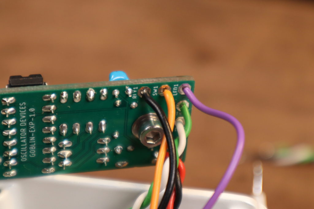
Next are all three wires of the bypass switch. The wire on the LED (purple) goes to LED1, the wire that originally was soldered to the switch (black) goes to RLY1 and the wire on the switch (orange) goes to SW1.
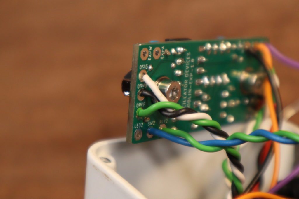
The MIDI out socket is wired with the white wire (tip) to OSIG, the green wire (ring) to OREF and the black wire (GND) to OGND. Also the wires for the mode switch are going to SW2 (the blue wire was the one facing the DC jack) and RLY2 (the green wire was the pin in the middle)
Last we wire the expression jack. The orange wire (tip) goes to the wiper EXPW, the white wire (ring) goes to EXPA on the Goblin.

And that’s it for the wiring. Now we can reassemble all nuts and knobs and fasten the Goblin. As you see, it’s kind of crowded in there. Also don’t forget to cut off the excess of the wires on the other side of the PCB, because they can create a short on the enclosure.
Step 10: Expression Socket
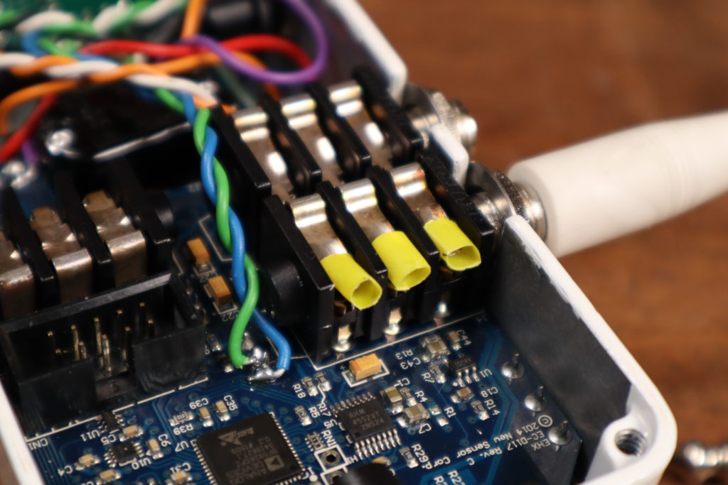
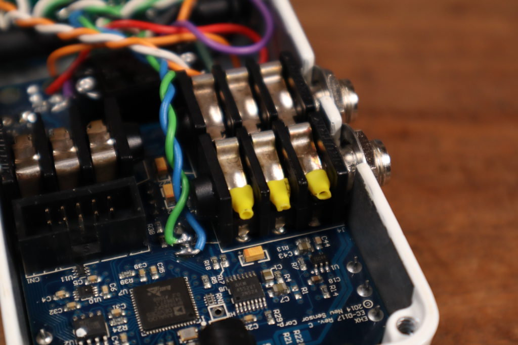
The Expression function of the Pitch Fork only works, if a jack is inserted. So either, you insert a jack everytime you want to use the expression function (a dummy plug is available in the shop) , or we have to trick the Pitch Fork in thinking a jack is inserted. To do that, insert a plug, take some shrinking tube and put it over the tips of the lugs like in the picture. Apply some heat and you’re good to go. This is easily removed and the jack does still functioning from the outside.
Step 11: Configuration
If you just bought that Goblin-EXP and it’s in its default configuration, you can skip the configuration and you’re done. Congratulations.
All new Goblin-EXP are set for the Pitch Fork at default. If you install in another device though, I’ll go through the configuration process below.
To configure the Goblin-EXP we send a bunch of MIDI CC messages. Usually it is a group of four messages. The first message is the actual configuration command. The second and third messages are a passcode, so we don’t accidentally change something. The fourth message is the save command, which burns the configuration to the memory. These four messages have to be send in a row, without any other messages in between. To take action the Goblin has to be restarted. All this is also described in detail in the installation manual.
Bypass
We connected the bypass switch on Port 1. So we need the role Switch for port 1.CC 27 02 CC 09 18 CC 09 52 CC 09 01
Also, we measured the LED and found that the voltage of the LED on the active pin is higher when switched off, then when switched on. So we have to invert the LED sensing.CC 28 00 CC 09 18 CC 09 52 CC 09 01
We measured two values of the LED, 3.3V and 1.5V, so we set the LED threshold to the mean value of 2.4VCC 29 47 CC 09 18 CC 09 52 CC 09 04
Mode Switch
For the mode switch we need to set Port 2 to role TRS normally openCC 47 04 CC 09 18 CC 09 52 CC 09 02
Expression Function
To use the Pitch Fork without MIDI, we need to set the startup value of the expression function so it does not interfere with the normal operation. On the Pitch Fork we set the startup state of the expression function to toe position.CC 59 01 CC 09 18 CC 09 52 CC 09 03
Find the CC commands to control the Pitch Fork here.