This page is for all who struggle with the admittedly brief installation instructions of the Imp/Goblin. I will explain all the concepts, show you all the measurements and get into the configuration deeply. This is meant as an addition to the installation manual. Please take the actual manual as reference.
First we clarify the Ports and Roles concept, then we look at measurements and how to gather the information you need and in the end we bring that all together in the configuration.
Ports and Roles
At this point, we know what an Imp is. It’s the most basic of my devices. It controls (or replaces) exactly one switch. Shortly after doing the Imp it was clear that I need to do a device, that is two ore more Imps in one. This is how the Goblin was born. So basically, the Goblin is three Imps in one package. But we don’t call it Imps, we call it Ports. So when I say the Goblin has three ports, what I mean is, it can act as three seperate Imps. And that’s it, the ports of the Goblin act as three independent devices with three independent functions…or Roles.
The Ports of the Goblin became more than just Imps. They go beyond. They can do way more. To describe that fact, I introduced Roles. A role describes what a port can do…or a port can be. But, most importantly, the role of the port is not fixed, it’s configurable. Port 1 can have a different role than port 2 or port 3. They’re independent. And depending on the role the single terminals (that are the connections on the PCB called RLY, SW and LED) have different meanings.
The different roles are explained in the manual. But let me describe them again in more depth.
- Role Switch: This is the basic role of a Goblin-SPST and does basically what an Imp-SPST does. It controls a singel SPST-Switch. To do that it is wired between the actual switch and the effects device. But it’s important for the Imp/Goblin to know the state of the effects device (on or off) to switch accordingly when needed. For that the LED is used. It is the status indicator. The Goblin needs a connection to the LED for that. How that works and what we need to make it work properly we’ll see in the following chapters.
- Role Tap Tempo: What if my switch doesn’t care if it’s on or not? Do I need that stupid LED then? No you don’t and you can use the role tap tempo for that. Exactly the same as switch, but the terminal LED is left open. This is for all switches that don’t have an on or off state, like tap tempo switches.
- Role TRS: This is the role for switching stuff like footswitches but from the inside. If this role is chosen, two of the three terminals of the port are turned into switches on their own. That means, that these particular terminals can be connected to GND by a MIDI command. That corresponds to a closed switch. Let me give a example. Small Strymon pedals like the Flint have a 1/4″ socket for a Favorite-Switch. This favorite switch is a regular footswitch. If you press it, the tip of the 1/4″ is connected to the sleeve of the plug which is connected to GND. Using the Goblin, installed inside, we can solder a wire to a pin of this favorite socket on the PCB and connect it to a TRS terminal of the Goblin. The Goblin then can MIDI controlled pull it to GND and activate the favorite function.
- Role Encoder: Since version 1.0.1 the Goblin is capable of controlling an encoder wheel, like in the EHX POG2. Encoder wheels like this have two pins for the rotation (You can look up how encoders work, if you interested in that). There is also a pin for a switch for the push function. So, if you use that, the Goblin simulates the turning of the encoder wheel and push of the button.
- Role Relay: This is the most straight forward role. It’s basically an Imp-3PDT. This role apparently only makes sense if a relay is installed on that port and is only for Goblin-3PDT on port 1 and port 2.
Ports and their MIDI commands
Every port has the same command set, meaning the same functions, but they’re using different CC numbers, or commands. So the command for switching on and off for port 1 is CC 10. For port 2 it’s CC 30 and for port 3 it’s CC 50. You see, they’re 20 apart.
Depending on the role, the command set may be different. But port 1 always starts at 10, port 2 at 30 and port 3 at 50. The commands below 10 are commands that are not specific to a certain port.
Initial measurements and gathering information
As the manual states, you need to know a few things before you start installing the Imp/Goblin. The following chapter is only interesting for the roles Switch and Tap Tempo.
The originally installed switch has two wires. Normally one goes to GND and the other one is connected to a certain voltage. This voltage can be 1.8V, 3.3V or 5V or something else. We should check that this voltage is not higher than 5V (well, 5.1V is not bad, 9V would be bad), because that could damage the Imp/Goblin. 5V and everything below is absolutely OK.
To measure this voltage, open up the pedal, connect it to the power supply and take your multimeter set to voltage mode. Measure the voltage on both lugs of the switch. One will be 0 volts, the other not. We call the latter the active lug.
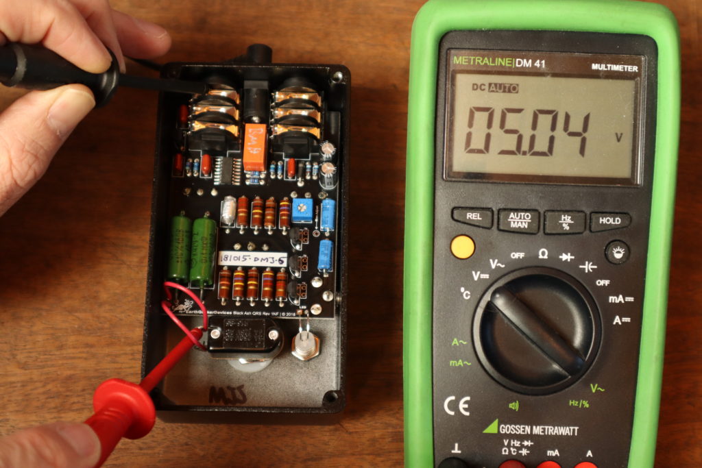
Now we have the first important information. The active lug is the one where we desolder the wire from the switch. We connect the terminal SW to the lug of the switch and connect the desoldered cable to RLY of the Imp/Goblin.
We have gathered another important information. If everything is as explained above, you have a “Normally Open” switch. This will almost always be the case. If you measure the same voltage (or measure nothing at all) on both lugs, you probably have a “Normally Closed” switch.
Next thing is the LED. The LED is used to check the state of the effects device. Let me explain why this is important. The Imp/Goblin is only be able to do one single action. Switching. But is it switching on or off? This is important. If you send the MIDI message to turn your effects device on, the Imp/Goblin has to know if it has to switch, or ignore this message because the device is alreday on.
To solve this, the Imps/Goblins have a way to measure voltage. A good way to check if the effect is on is to check the status LED (or the voltage of the LED). We take our multimeter set to voltage and measure both pins of the LED when turned on and when turned off. Be sure to measure to GND, because the Imp/Goblin also measures relative to GND. Do not measure between both pins!
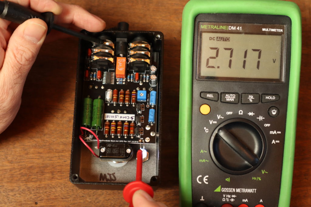
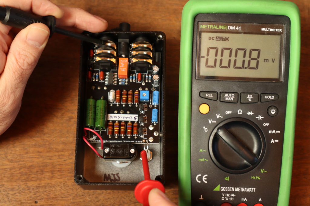
You’ll notice that one pin of the LED will change it’s voltage when switching. This is the active pin and that’s the one we’re interested in (this is not always the pin with the higher voltage). This is also the one where the terminal called LED on the Imp/Goblin is connected to. But don’t desolder anything, just wrap a wire around it and fix it with solder or solder it to pin on the PCB.
The ways LEDs are wired can be wildly different. On the pictures above, it’s very easy and clear. LED off = 0V, LED on = more than 0V. But it’s not always like this. So write down what you have measured, we need that later.
The other important information we gathered is, if our LED is “High Active” or “Low Active”. Meaning, if the voltage is higher when the LED is on, than when off it’s High Active. When the voltage is lower when the LED is on, than when off it’s Low Active
For example, the one in the pictures above is High Active because a higher voltage is measured when the LED is on.
Configuration
Configuration is actually the part a lot of people are uncomfortable, or even struggle with. But it’s important to have the Imps/Goblins as flexible as possible because there are so many different effects devices out there. Every configuration point is born out of a need in reality (looking at you OBNE Dark Star).
To actually do the configuration you need a MIDI controller…well, if configuration has to be done, at all. Often times the standard configuration is just fine. I use a Morningstar MC6. This style of controller is very handy for this, because of its user interface. A DAW with a MIDI interface would also work. Of course, every MIDI controller will work, but I assume it could be a bit complicated with an ES-5/ES-8.
So, to proceed you need to have your Imp/Goblin wired up and the inital measurements taken. The first thing I do in this case is to check if the MIDI connection works and the Imp/Goblin is powered. This is most easily done by checking the MIDI Thru. To do that, connect a MIDI controller to the MIDI in and something else you already have working with MIDI on the MIDI out. Send a message and check if the other device reacts. If not, check wiring, if yes we can proceed.
The Imps/Goblins are deliviered in omni mode, that means they react to every MIDI channel and we don’t have to bother with MIDI channels now.
To configure the Imp/Goblin we send a bunch of MIDI CC messages. Usually it is a group of four messages. The first message is the actual configuration command. The second and third messages are a passcode, so we don’t accidentally change something. The fourth message is the save command, which burns the configuration to the memory. These four messages have to be send in a row, without any other messages in between. To take action the Imp/Goblin has to be restarted. All this is also described in detail in the installation manual.
Role
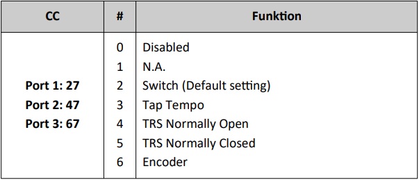
We now already know what the roles are. We need to set it up now. Look up the installation manual and check for the chapter with the configuration command for the role. It gives you a different CC command for every port of the Imp/Goblin. It’ll probably look something like the picture on the right. It gives you a CC command for every port. CC 27 for port 1, CC 47 for port 2 and CC 67 for port 3. The number in the column after that is a number, associated with a role.
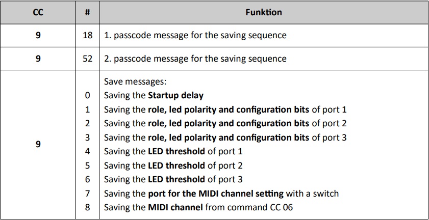
As stated above, we need a set of four commands. The next table gives us the three missing one. The first two lines are the passcode commands, the third line gibes us the save command. If we put all this together and, for an example, try to set the role to switch for port 2, we get the following four commands:CC 47 02 +CC 09 18 +CC 09 52 +CC 09 02
These four commands has to be sent to the Imp/Goblin in a row. Make sure no other command is sent in between. Restart the Imp/Goblin and at next power up the new role is saved.
LED Polarity
We learned before that the polarity of the LED is important for sensing the correct state of the effects device. The LED polarity can either be “High Active” (voltage is higher when on, then when off) or “Low Active” (voltage is lower when on, then when off). If you check in the manual, you’ll find a table, just like with the roles above, for that. Look up what you need and proceed like in the chapter above. First is the command from the table (CC 28, CC 48, or CC 68). MEssages two and three are the passcode like above: CC 09 18 +CC 09 52 . The save command is the same as for the role.
LED Threshold
Now there is the LED threshold that needs to be saved. That only is relevant for the role switch. The threshold value itself can again be calculated by this spreadsheet. Type in the values you measured in the blue boxes and the orange box gives you the ideal LED threshold to send to the Imp/Goblin. It also gives you the setting for the LED-POL configuration, but I guess we figured that out by ourselves by now.
Anyway, the same command structure is used than with the configuration above. The LED command, followed by two passcode commands, followed by a save command. Another example. We measured 0V when LED off and 2.7V when on, the spreadsheet will give you 27 (the ideal threshold is in the middle, so 1.35V and it’s in 0.05V steps).
The commands for port 1 would be CC 29 27 + CC 09 18 + CC 09 52 + CC 09 04
For port 2:CC 49 27 + CC 09 18 + CC 09 52 + CC 09 05
And for port 3:CC 69 27 + CC 09 18 + CC 09 52 + CC 09 06
You see? It’s the same, only that the commands for LED threshold are different and the argument for saving is different.
Startup Delay
To save a new startup delay is almost the same. The CC comand for the startup delay is CC 08 and the argument for the save command is 0. So, for 3s startup delay we send 30 (it’s in 0.1s steps).
That’d be: CC 08 30 + CC 09 18 + CC 09 52 + CC 09 00
Configuration Bits
For some strange pedals, there are a few special settings. These are the configuration bits. It can be used to set some configuration with only one set of commands, too. You’ll probably never need them and it’s going to be a bit complicated. But I’ll explain it anyway.
In the installation manual there is a table with so called configuration bits. It looks like this.

What we now need to do is to choose on of the options from every column for every port.
- ROLE: We got into the roles already, hopefully you know what to choose.
- POL-SW: What polarity is the switch? We gathered that information in the chapter before. Tl;dr it’s “Normally open” almost always.
- POL-FX: What polarity expects the side the switch is connected to. This is the same as POL-SW almost always! This is for the very, very rare case, that the effect is expecting a normally open switch and you want to use a normally closed switch. Never happened.
- FX-DRIV: This also is for some very rare occasions. It’s almost always set to Open-Drain. This means that the control voltage of the switch is supplied by the FX.
- POL-LED: We gathered that information in the LED part above. Tl;dr: If voltage on the LED is higher when on, than when off it’s High Active
Now, with all that information you can head over to this spreadsheet. It will calculate the command for you. Select the tab for the device and software revision you have (Goblin-1.0.0 for 2021 and Goblin-1.0.1 for 2022 and later devices) and simply select the dropdown menus of the blue fields. You’ll see a number in the orange fields, these are the combined configuration bits. For furhter reference let’s call it the configuration word. In this single number is a particaular combination of the above options encoded.
As mentioned before, we now have to send this configuration word to the Imp/Goblin. But a single command is not enough, we need a set of commands. These are security measures that you don’t overwrite your settings in a normal use case. The command set consist of 4 single commands.
- The first command is the configuration word itself, sent to the port it is meant for. Every port has a command for that.
CC 19for port 1,CC 39for port 2 andCC 59for port 3. - The second and third command is a password. These commands are always the same, regardless which port. The commands are
CC 09 18andCC 09 52 - The fourth command is the save command. It’s
CC 09 xxwithxxsaying what it is to be saved. LikeCC 09 01for saving the configuration of port 1. Check the manual for all options.
These four commands have to be sent directly after another without any other command in between. The changes only take effect after the next boot up.
Let’s have a look at a real example. Say the configuration word is 58 and I want configure port 1. The CC commands would be: CC 19 58 + CC 09 18 + CC 09 52 + CC 09 01
If you use a Morningstar MIDI controller, this is what it would look like in the editor:
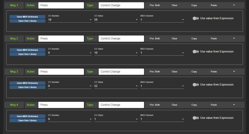
So, if you would set your Morninstar controller to the above and press that switch with a Goblin connected, it would be configured (in that case for role switch, normally open POL-FX and POL-SW, open-drain FX_DRIV and low active LED-POL).
The same configuration at port 2 would look like that:CC 39 58 + CC 09 18 + CC 09 52 + CC 09 02
And for port 3 like that: CC 59 58 + CC 09 18 + CC 09 52 + CC 09 03