This is an assembly instruction for the Goblin-SPST and the Strymon El Capistan. Recent versions of the El Capistan have MIDI support and thus this guide is somewhat deprecated, but it can be used as a guideline for installation of the Goblin-SPST in other devices. I’ll go into details whenever there are differences to expect.
Preperations
Make sure you have the following tools handy.
- Philips Screwdriver
- Allen wrench 2mm
- Metal drills 3.3 mm and 8.5 mm
- Soldering iron and solder
- Wire stripper and pliers
- Multimeter for voltage measuring
Step 1: Measurements
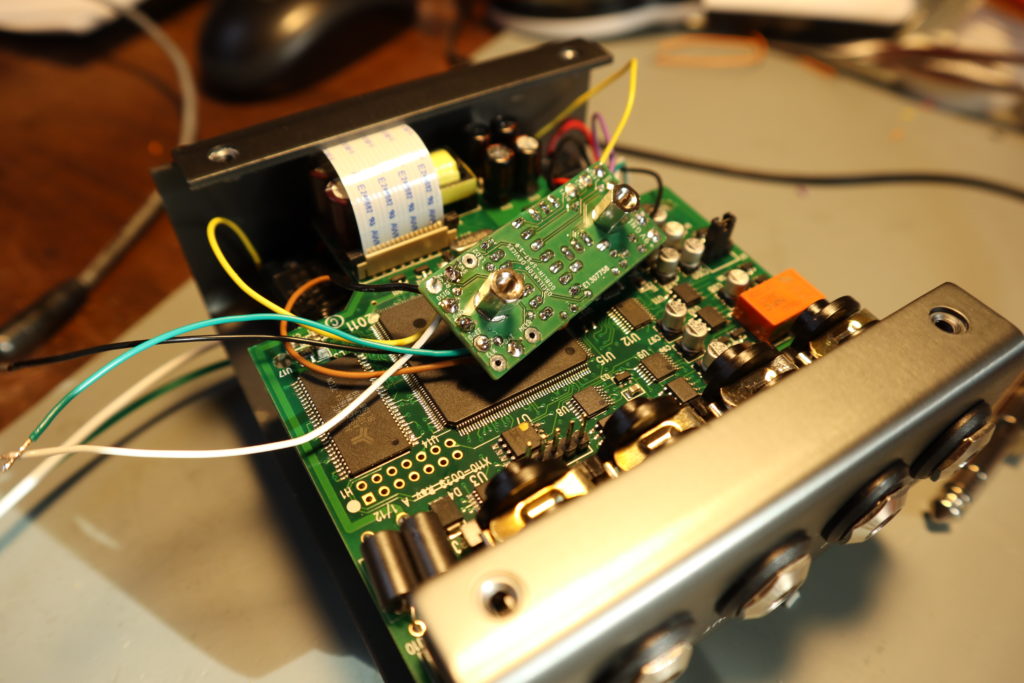
Unscrew the Bottom plate and remove it. Before we proceed, we need to make some measurements with the multimeter. Both measurings are to be made with the pedal powered on. Be careful not to short anything.
- Find out which side is the positive side (+5V or +3.3V) of the switches. If you push the switch, the positive side should go down to GND. If this is not the case, refer to Appendix 2.
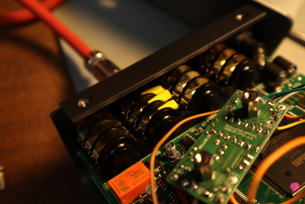
- Find out which is the active pin of the LED. Measure the voltage on both LED pins to GND (the ones in the picture below). One pin should always be the same voltage. On the other pin the voltage will change when the LED is on vs. off, this we cvall the active pin. Measure the voltage when it’s on and when it’s off (on the El Capistan it should be around 1.5V when on and 2.0V when off). If you’re working on something different than a Strymon pedal, refer to Appendix 1.
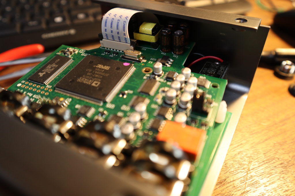
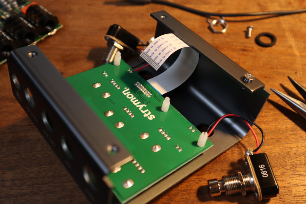
Step 2: Disassembly
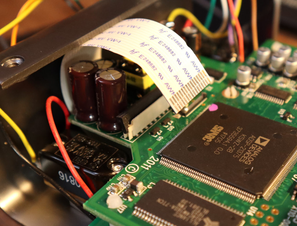
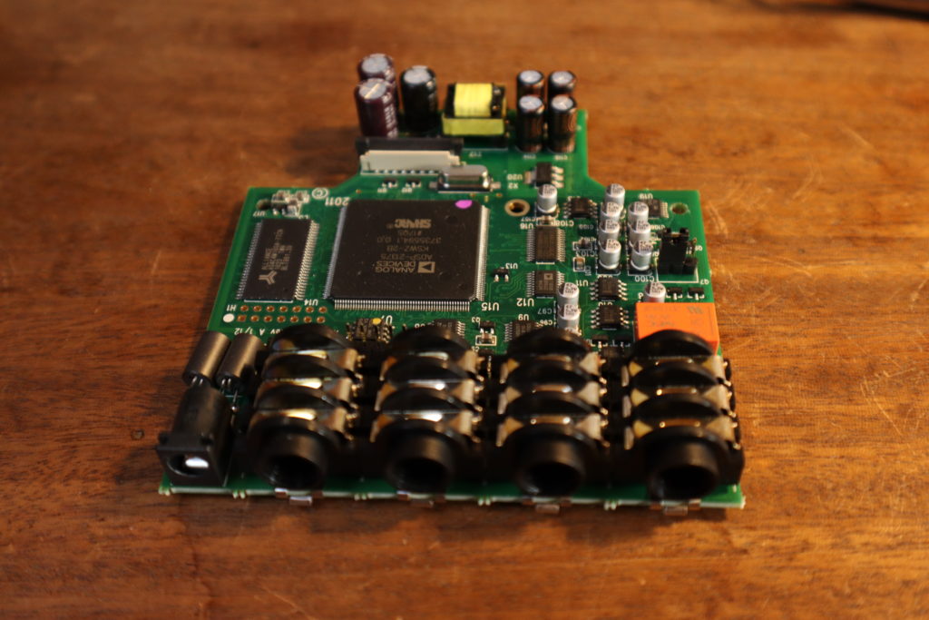
Remove the nuts of the top side sockets. Carefully push up the two black lugs on the ribbon cable socket to unlock the ribbon cable and remove it. Threre are three plastic standoffs, that need to be dealed with. These are nasty, be careful not to break them and deal with them one by one. Take a plier or strong tweezer and pinch together the top and gently push until the PCB comes out. Slide out the PCB.
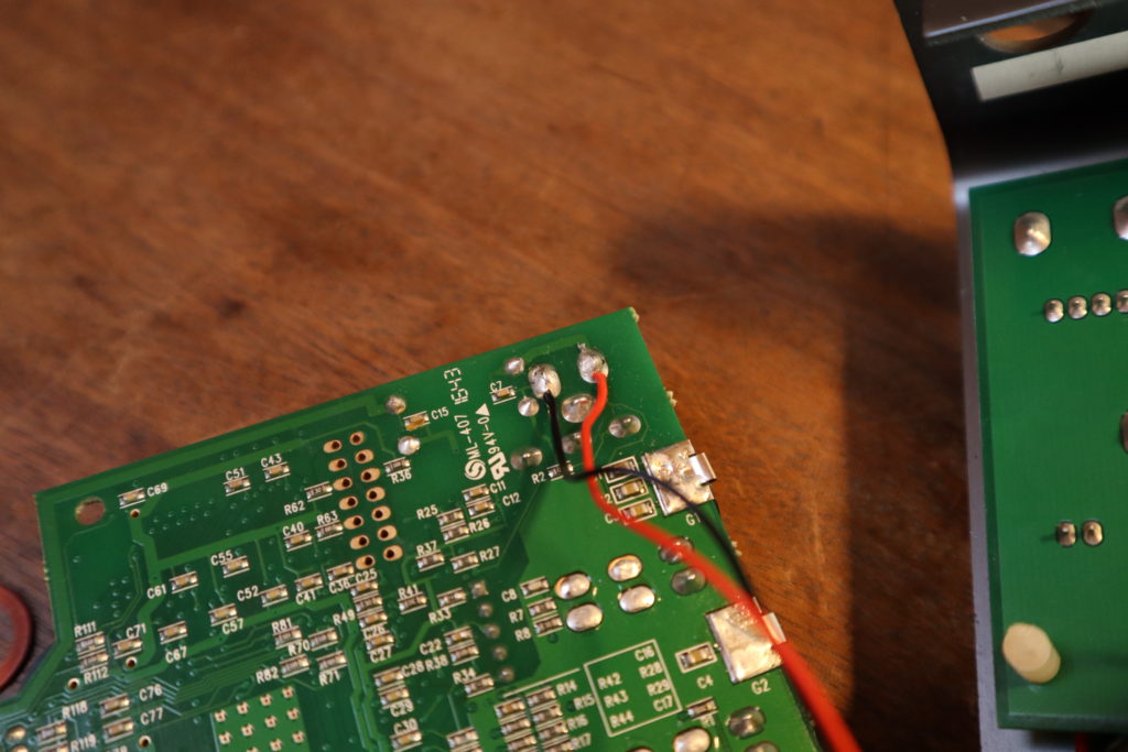
Step 3: Soldering of power supply
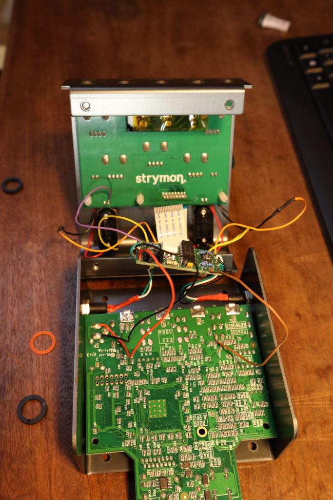
Solder the red wire to the positive supply and the black wire to the GND connection of the power jack. If the old solder won’t flow properly, use some additional fresh solder. Connect the wires to +9V and GND of the Goblin.
Step 4: Wiring of the bypass
The bypass switch should be connected to port 1 of the Goblin. It needs three connections.
- From the switch to the Goblin: Desolder the positive wire, we measured in Step 1, from the switch. Connect the lug of the switch to SW1 of the Goblin.
- From the Goblin to the El Capistan: Extend the desoldered wire (still connected to the PCB on the other side) from the El Capistan and connect it to RLY1 of the Goblin. You can use the wire without extension, but it’s a bit short.
- From the LED to the Goblin: This one is needed, so the Goblin can check, if the El Capistan is on or off. Connect the active side of the LED we found out in Step 1 to LED1 of the Goblin.
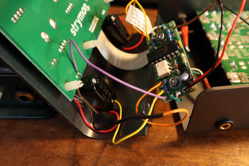
Step 5: Wiring of the tap tempo
The tap tempo switch is like the bypass switch, but the LED wire is not needed. We connect it to port 2.
Proceed like the bypass switch but leave LED2 open. If you have a different pedal, than the El Capistan, the second switch might be a regular switch, too. In this case connect the LED like in Step 4.
Step 6: Wiring of the TRS jack
We connect the TRS jack to port 3. Since the El Capistan has only the Tip of the EXP socket assigned, we only need one wire. Connect the tip of the TRS Socket to DAT on the Goblin. In case you’re having a pedal with the ring assigned, connect it to CLK on the Goblin.
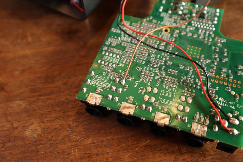
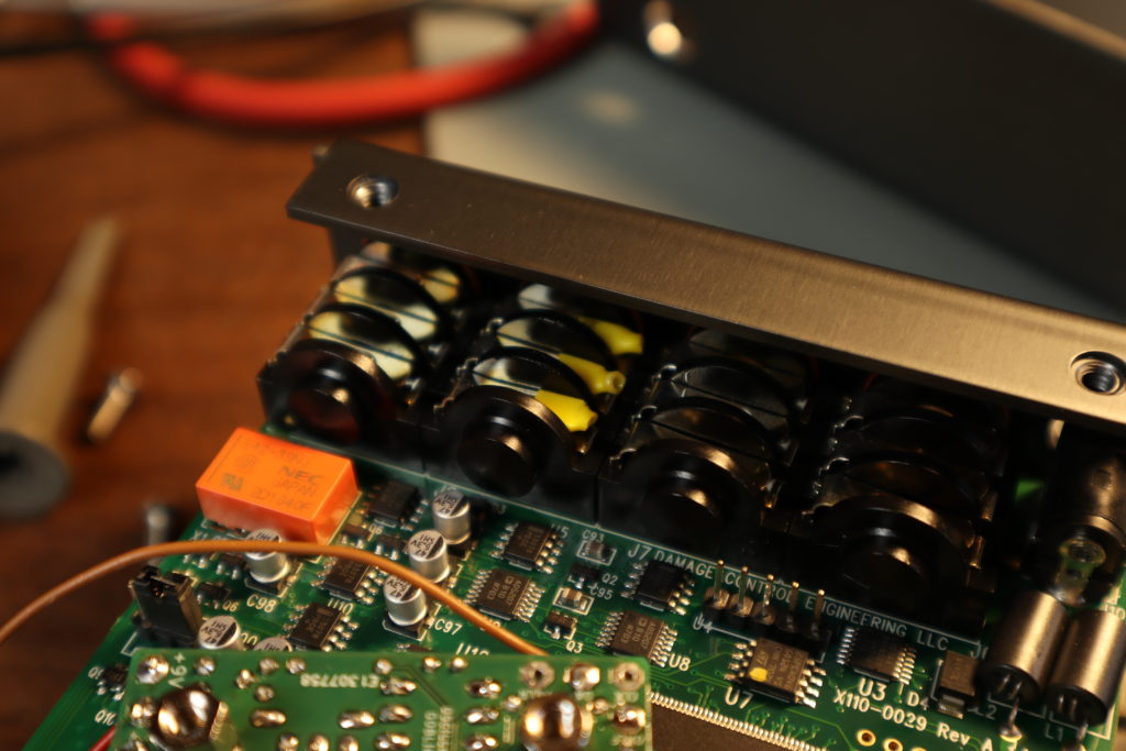
The EXP socket of the El Capistan only works, if a jack is inserted. So either, you insert a jack everytime you want to use the port (which would be lame), or we have to trick the El Capistan in thinking a jack was inserted. To do that, insert a plug, take some shrinking tube and put it over the tips of the lugs like in the picture. Apply some heat and you’re good to go. This is easily removed and the jack does still functioning from the outside.
Step 7: Assembly
Best assemble a few parts before you proceed. Mount the switches, slide the PCB back in (don’t forget the washers of the top jacks), put in the ribbon cable and carefully tighten the sockets. Put in the screws for the top jacks and push the PCB back onto the standoffs.
Step 8: Drilling
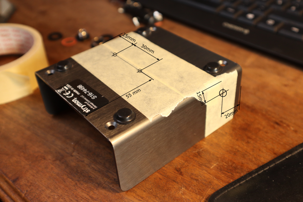
Are you ready to drill some holes in a 300+€/$ pedal? Good! For the fastening screws you need a 3.3mm drill and a countersink. For the MIDI sockets a 8.5mm drill is required. Put masking tape on the housing and carefully mark the holes like pictured. If you have a different pedal than the El Capistan, you might move the drillings a bit. You can leave out the MIDI Thru port if you don’t need it.
Use the countersink to sink the screw heads of the mounting screws. Make sure to debur the edges and make sure, that no chips are left inside the housing.
Step 9: MIDI-Sockets
Now we need to prepare the MIDI sockets by soldering wires to it, like in the pictures below. The MIDI in socket doesn’t have a GND/Sleeve wire. You can remove the lug altogether.
In the picture the white wire goes to the tip, the green wire goes to ring and black to sleeve.
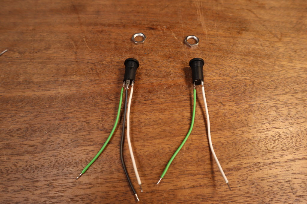
- MIDI In: Connect IREF to ring and ISIG to tip, leave the sleeve open
- MIDI Out: Tip to OSIG, ring to OREF, GND to sleeve.
Step 10: Startup and configuration
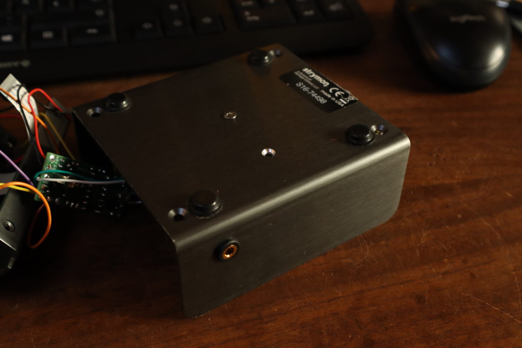
After screwing the Goblin to the bottom plate and screwing the bottom plate back on, it’s time for the fun part.
If you have a complete blank Goblin, your pedal now makes some funny stuff. But don’t worry, it just needs a bit of setup. First check if the bypass button works. Then we check, if the MIDI In port is working. The Goblin is set to omni channel upon delivery, so MIDI channel doesn’t matter (don’t forget to change that later). Now, send command CC 10 02. Something has to happen now with the bypass. If not, go back and check the wiring.
To configure the Goblin we send a bunch of MIDI CC messages. Usually it is a group of four messages. The first message is the actual configuration command. The second and third messages are a passcode, so we don’t accidentally change something. The fourth message is the save command, which burns the configuration to the memory. These four messages have to be send in a row, without any other messages in between. To take action the Goblin has to be restarted. All this is also described in detail in the installation manual.
ATTENTION: These only work for Goblins purchased after July 2022. Earlier units have a different configuration procedure.
- Set the startup timer to 5 Seconds:
CC 08 50,CC 09 18,CC 09 52,CC 09 00-> Restart - Configure Port 1 for inverted LED:
CC 28 00CC 09 18CC 09 52CC 09 01-> Restart - Configure Port 1 LED threshold to 1.75V:
CC 29 35,CC 09 18,CC 09 52,CC 09 04-> Restart - Configure Port 2 as tap tempo:
CC 47 03CC 09 18CC 09 52CC 09 02 - Configure Port 3 as TRS NO:
CC 67 04,CC 09 18,CC 09 52,CC 09 03-> Restart
Now, as the final step, plug in another MIDI device to the MIDI Thru port and check if it works. And you’re done!
Appendix 1: Weird LEDs
There are some cases of weird LEDs and the El Capistan is one of them. The use case the Goblin was designed for is, that there is voltage at the LED if it’s on and no voltage if it’s off. Simple enough. The El Capistan as well as most Boss pedals use a different circuit and our measurements will not work that way. Not only is there voltage on the LED if the effect is turned off, it is higher then when it’s on. To be ready for this case, I made the polarity as well as the threshold configurable. Here is how you configure it correctly:
Measure the voltages of the active side of the LED. That is the side that changes its voltage, when the effect is on vs. when it’s off. Is it higher, when switched off, set the LED-Polarity to Low Active. Take the mean value of both measurements and divide it by 0.05V. This is the LED Threshold. Send this value to CC 29 (CC 29 for Port 1, CC 49 for Port 2 and CC 69 for Port 3) and save it. with CC 09 18, CC 09 52, CC 09 04/05/06.
Heres an example from the Boss SY-1.
Measurement when on: 1.6V
Measurement when off: 2.0V
Configure Port 1 for inverted (Low Active) LED CC 28 00, CC 09 18, CC 09 52, CC 09 01 -> Restart
Configure the LED threshold halfway between 2.0V and 1.6V -> 1,8V -> 1,8V/0.05V = 36CC 29 36, CC 09 18, CC 09 52, CC 09 04 -> Restart
Appendix 2: Weird Switches
In very, very, very rare cases, manufacturers use different systems for their switches, I encountered this only once on a OBNE Dark Star. I made the Goblin configurable to fit such cases. This is one case where you need the configuration bits, so let’s call this part Advanced.
Some pedals don’t switch to GND. That means, if you measure the switch like in step 1, you measure a +5V side, but when you push the switch both sides go up to +5V instead of GND. In this case (but only in case we deal with +5V), remove the wire that is always +5V entirely and connect the other wire to RLY1. Connect one side of the switch to SW1 and the other to GND. You then have to set the FX-DRIV bit to 0. The Goblin now drives +5V. You also have to invert the RLY1 Port with setting the POL-FX bit to 0.
Let me make this an example how to get the configuration bits right:
- ROLE = 2 (We want Switch)
- POL-SW = 1 (Normally Open)
- POL-FX = 0 ( Normally Closed)
- FX-DRIV = 0 (Push Pull)
- POL-LED = 1 (High Active)
Now we need to get all this together to a binary word. ROLE is the three LSB (Least significant bit). Also 2 is not binary, 010 is binary for 2. So we get: 1 1 0 0 0 1 0
We now have to convert this to decimal, it’s 98. So your configuration commands look like this for port 1:CC 19 98, CC 09 18, CC 09 52, CC 09 01 -> Restart